
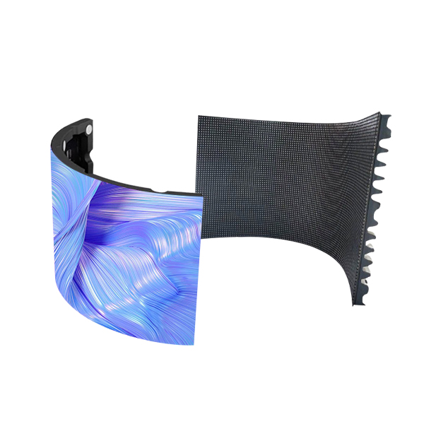
To make an LED display screen, the first step is to prepare sufficient materials. Now, let’s create an installation, production, and manufacturing process for an LED display screen, explaining in detail the required materials and the process of the display screen. A display screen covers the outer frame, display area, control area, power supply area, and small accessories.
1. Partial outer frame: special aluminum profiles, corners, light steel keel, rear panel (aluminum-plastic panel, European pine panel are both acceptable)
2. Display local: Unit board. The attachment includes: ribbon power cords.
3. Control local: Control cards, adapter boards, and cables. Attention! (Some control cards do not require adapter boards and cables)
4. Local power supply: 220V to 5V power supply. The commonly used ones are 40A and 30A. It depends on the starting work situation.
5. Small accessories: 16P ribbon cable, 16P card head and clip, three core numerical cable, DB9 head (pin, hole) DB9 rubber shell, power cord, self tapping wire. Strong magnet (support column and magnetic sheet)
6. Tools: cutting machine, wire crimping pliers, soldering iron, wire stripping pliers, screwdriver.
Assembly steps
To make a good display screen, the first step is to confirm the volume of the frame. Below, I will explain the method of cutting the frame. Taking the most commonly used 3.5 * 90 profiles and P10 unit boards as examples. The display screen has a volume of 2 * 5 pieces.
1. Confirm the size of the unit board, which needs to be very accurate to millimeters. Take the P10 unit board as an example: its size is 16cm * 32cm.
2. Calculate the net dimensions of the height and width of the unit board inside the display screen. For example, the height is 2 pieces * 16cm=32cm and the width is 32cm * 5 pieces=160cm
3. Subtract 4mm from the calculated net size. As mentioned above, the net size is 32cm * 160cm. Therefore, the size of the aluminum material should be (32cm-4mm) * (160cm-4mm)=31.6cm * 159.6cm. 31.6 and 159.6 are the actual dimensions of aluminum, and if the display screen exceeds 3 meters, 5mm needs to be subtracted.
4. Use self tapping to connect the corners and cut profiles, thoroughly tidy up any debris, and place them face down.
5. Place the unit board in the correct direction, without making any mistakes. The place with pins must face the height of the profile.
6. Install the magnet support column onto the unit board and feed the magnetic sheet into the concave groove of the nursery column.
7. Measure and cut the required length of the light steel keel, place it on the magnet, and try to keep the magnet in the center of the keel to avoid distance deviation.
8. Use self tapping to connect the keel with the frame.
9. Use ribbon cables to connect the unit boards in a bridge shape, and do not allow the ribbon cables to be buttoned.
10. Fix the power supply in the appropriate position inside the profile, and confirm where to place the power supply according to the following instructions. The power supply is usually placed on the profile below the display screen. Pay attention to the insulation with the unit board.
11. Sign the power cord, and the power cord should not be illegible. The exposed screen is certainly a low-voltage office, but the current is very high. It is not allowed to come all the way in parallel. A P10 unit board has a full current of 4A, which means that a 40A power supply can carry ten unit boards. The display screen is connected in parallel, with the positive pole connected to the positive pole and the negative pole connected to the negative pole. Normal VCC,+5V,+V is the positive pole. GND, COM, – V are cathodes. And the positive and negative electrodes must not be connected incorrectly, otherwise it will cause the unit blackboard to be scrapped. Example: A 40A power supply comes with 10 unit boards. We can divide them into three and connect them together to the power supply at 5V once, then connect them together to the power supply at 5V once, and finally connect them together to the power supply at 5V once. That is to say, each circuit should not exceed 4 unit boards, so that the wires will not be damaged due to excessive current.
12. Place the choke card at the input end of the unit board and ensure that 5V power is directly supplied from the power supply.
13. The pins of the choke card are sorted in order. The position of JK1. JK2… or J1. J2… JP1. JP2… should be connected to the top unit board at the input end of the unit board according to the arrow.
14. Joint signature of unit board and control block: There is a small white letter A around the first pin of the ordinary control card, and there are also such characters on the input end of the unit board. As long as the two A’s are connected in parallel with a ribbon cable, it is accurate.
15. After completing the above tasks, the debris inside the screen must be thoroughly cleaned up to avoid conductive aluminum powder, iron powder, and wire ends falling into the circuit board and causing damage to the unit board.
After thoroughly organizing the work, conduct a power on test, provided that the numerical lines are properly prepared. Due to the fact that most digital control card printing shows abnormalities before the values are changed. So when encountering symbols that appear messy after being powered on, such as dim or bright spots, don’t be arrogant. As long as you confirm that the positive and negative electrodes are not connected incorrectly, there is no need to worry about it.
17. Welding method of numerical lines: Ordinary display screens only use two of the following three types. Extension cable: This is required for every display screen. As the name suggests, its function is to extend the numerical interface of the choke card outside the display screen. Since your display screen will eventually have to be sealed with a back cover, you can’t change the data and remove the back cover again! The materials he needs include: a three core wire that doesn’t have to be very long, a DB9 pin, and a DB9 hole. The number 6789 is marked above the soldering area behind each DB9, and we only need to sign three of them together. These three are the two pins of 235 and the two holes, which are soldered together with one of the three core wires inside. 3 and 3 are welded together, while 5 and 5 are welded together. Once done, install the rubber shell onto the end with the needle (as the hole is inside the screen), and that’s it!
The welding method for two non intersecting lines is the same as that for the extension line, but the difference is that two DB9 holes are used for the two non intersecting lines, both of which require adhesive shells. The material of the intersecting line is the same as that of the two non intersecting lines, with the difference being that the 2 of the intersecting line is connected to the 3 of the other line and the 3 is connected to the 2 of the other line, while the 5 is still connected to the 5. It also requires two rubber shells on the heads.
18. The intersecting lines and non intersecting straight lines are voted based on the use of restraint cards to determine whether they are parallel or intersecting.
After completing the above office tasks, the remaining adjustment is necessary, provided that the display screen has the ability to be powered on and adjusted. Due to the large number of regulated card categories in the market, I will not introduce them.
After adjusting and testing for 2-5 days, if there are no problems, the back cover can be cut and sealed. Finally, we can deliver!
Installation, production and manufacturing process of LED display screen